Here is a video with it in action:
Wednesday, January 10, 2018
Bluetooth fidget cube
Recently I was made aware of the fidget cube. However the cube doesen't seems to do anything so as a request from somebody, I decided to modify a bluetooth VR box controller and insert it in a cube.
Here is a video with it in action:
Here is a video with it in action:
Sunday, November 22, 2015
Mini plotter based on arduino
The technology is advancing very fast, allowing almost anyone to build CNC routers and 3d printers.
In the past years, a CNC machine was a very complex machine, the same was when the first 3d printers were released.
However, now it is relatively easy to build one of those two.
Recently i found some tutorials on how to build a mini plotter with two dvd drives, one arduino board, and two L293D motor drivers.
Unfortunately i did not make photos on the building process, but for who is interested here is a detailed tutorial, similar with what i did: http://www.instructables.com/id/Mini-CNC-Plotter-Arduino-Based/
What i did not had, was the servo motor, so my plotter could not lift the pen from the paper. However i don't think that is a problem, because i plan to mount a burning laser instead of a pen, to engrave text or cut slim pieces of plastic.
Here are two videos with the plotter in action:
I am planning on building a big version of this, with NEMA stepper motors.
Saturday, November 7, 2015
NFC shortcut button
What i enjoyed on old devices such as Psion series 5, HP Jornada 720, and other qwerty devices, was the shortcut buttons:


Those buttons allowed me to quick jump form word to calendar, or mail with a singe touch of a button.
I'm not exactly sure when those useful buttons were removed from devices, the last smartphone that had them, i think, was Nokia E90 communicator (which is unfortunately is no longer working due to broken flex cables).
The past is the past, we will never see those shortcut buttons again.
However there is a way to have the same functionality on a today smartphone. The solution is NFC (near field communication) technology.
There are several apps on google play that allow the write of NFC tags. Those app can write a link, a shortcut to a file, or a shortcut to an application to a NFC tag.
The NFC technology works by power a small chip, which can store a few hundred of bytes of information, by radio frequency at 13.56 MHz.
In order to red or write a tag, that tag must be at a small distance from the nfc anthenna.
On smartphones the idea is to put the back of the phone on a tag and get the information from it or write it.
I saw in this a possibility of bringing back the functionality of those old shortcut buttons, but for this i needed to modify the tag by cutting its anthenna and then add a button which, when pressed, reconnects the anthenna:


Here is the complete tag with the button soldered:

I put this tag under a silicon case on the back of my note 4. But because the case was made of transparent plastic, and the modified tag didn't look very good, i decided to print some pictures with the application that the tag launches:


I simply put the paper on the tag just to mask it. I can write any application i want on the tag, so if i am browsing the web and want to quickly check my email, i simply press on the tag button and i'm on the mail.
And here is it, those very useful buttons are now back. I did this only with one button for test, but i can put several tag with buttons on the back of the phone.
Here is a video with the tag in action:
I will post a video with more buttons on the back of the phone.
Mini multimeter based on Arduino


The principle is simple since it is possible to measure voltage directly with the analog inputs. However there is the maximum 5V limit that can be applied to the input. So i used a 100 K ohm resistor. Here is the diagram:

The source code can be found here: https://www.arduino.cc/en/Tutorial/ReadAnalogVoltage
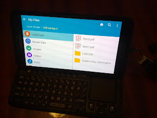
Again i modified the code to display the data on the nokia LCD and combine this code withe the first two, and the end result is a portable multimeter, which work quite good (there are limits in its accuracy), but for a quick measure is good, and very portable.
Here is a video with the multimeter in action:
The first development board i came in contact with was the Raspberry Pi, a few years ago. After building a tablet and a home automation system based on that board, i came across Arduino.
This because i had a work project that had to boot instantly (raspberry boot time is longer than a minute). It was a counting system for a conveyor, that can send the counted data to a server by ethernet.
Arduino is different of Raspberry, first because of the programming language. For Raspberry the main programming language is Python, while for Arduino is C, the other main difference is that Raspberry uses an operating system, while arduino only runs C programs, it does not run an operating system. Arduino bassicly a single chip microcontroller.
The main advantage of this board over Raspberry is that this have 6 analog ports, without any analog-to-digital converter.
After a few weeks of playing with arduino, i finished the counter project, and i learn a lot about this board, but what sparked my interest was connecting a Nokia 3310 LCD and display a text.
You can find more information about this here: http://playground.arduino.cc/Code/PCD8544
Here is the pinout diagram:

As you can see, in order to make the display to work properly, i had to solder a 10 uf capacitor between the Vout and GND pins. However on some lcd models that capacitor is not really necessary.
While i searched for more details about the atmega 328 (the arduino microcontroller) i found the Reduino core:

It is just like a Arduino uno board, but as basic as possible, with the Atmega cpu and the crystal. Also this board can be powered with no more than 5 volts.
To program it it is necessary to connect it to an arduino uno board:

It is perfect for small devices, or automation systems where the space is very small.
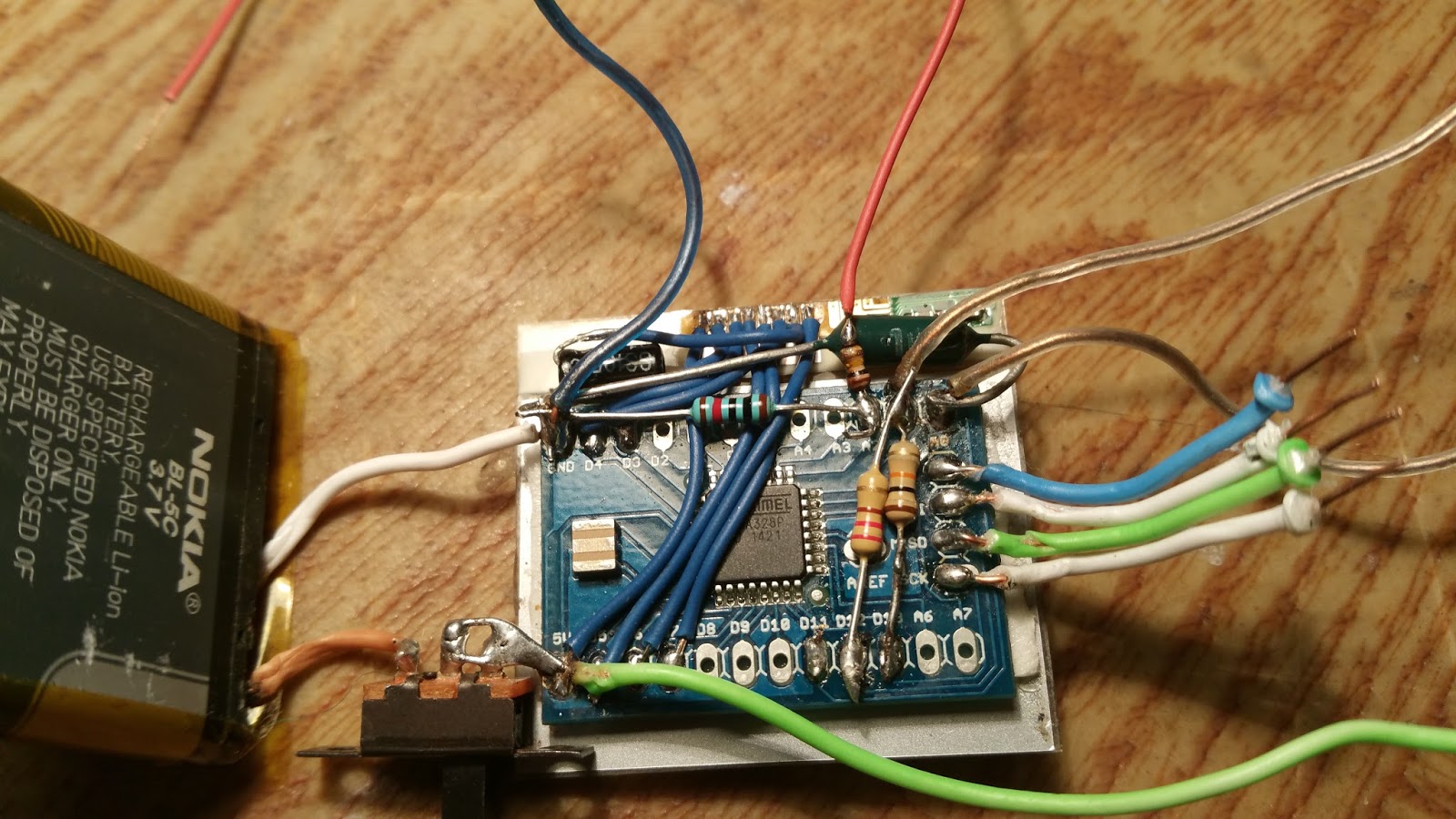
After i ordered several of this small boards (they are also very cheap), and because i had a spare Nokia 3310 lcd, i decided to create a small portable multimeter.
This is possible thanks to the built in analog inputs which can directly measure voltage up to 5V.
So i got a BL-5C Nokia battery to power the reduino board, (it does not deliver 5 volts, but it power the arduino and the nokia lcd quite well).
A small switch is connected to the + of the battery in order to turn it on/off . The 4 wires are plug in the arduino uno for reprogramming. Here are a few pictures of the building states.


1 Ohmmeter
Arduino can measure, with the analog inputs, the voltage at the middle of two resistors.
The schematic is very simple:

The arduino reads the voltage at the selected analog pin (A0). This voltage cross the resistor which is being measured.
You can find the source code of the ohmmeter on google. Here is one example: http://www.circuitbasics.com/arduino-ohm-meter/
What i did was to modify the code according to the voltage supplied by the battery (arduino works with 5V, but my battery can supply only 3.7 to 4 volts), and add some lines to display the value of the resistor on the nokia LCD.
2. Measure capacitors
After the the the small device could measure resistors, i decided to enhance it further by adding the posibility to measure capacitors.
The working principle is by measure the charging time of the capacitor.
The schematic and the source code are from here: https://www.arduino.cc/en/Tutorial/CapacitanceMeter
I modified the code, as was the case of the ohmmeter, and combine the two programs into one and upload them in the Reduino.
3. VoltmeterAfter the the the small device could measure resistors, i decided to enhance it further by adding the posibility to measure capacitors.
The working principle is by measure the charging time of the capacitor.
The schematic and the source code are from here: https://www.arduino.cc/en/Tutorial/CapacitanceMeter
I modified the code, as was the case of the ohmmeter, and combine the two programs into one and upload them in the Reduino.
The principle is simple since it is possible to measure voltage directly with the analog inputs. However there is the maximum 5V limit that can be applied to the input. So i used a 100 K ohm resistor. Here is the diagram:

The source code can be found here: https://www.arduino.cc/en/Tutorial/ReadAnalogVoltage
Again i modified the code to display the data on the nokia LCD and combine this code withe the first two, and the end result is a portable multimeter, which work quite good (there are limits in its accuracy), but for a quick measure is good, and very portable.
Here is a video with the multimeter in action:
This is the first version, i am going to make a plastic case for it and some sockets for probes.
Sunday, August 9, 2015
Turning Samsung galaxy note 4 (SM-N910F) into a mobile pc - Part 3 - usage
Well, it's been more than a month since i finish the construction of the keyboard case. Since then it was always on the phone. It's now time to say what i think of it.
The battery of the keyboard does last long especially if i turn it off when i'm not using it. What i was pleased to discover, was that if i turn on the keyboard, it connects to the phone almost instantly.
Typing on this keyboard requie some getting used to, becase of the large size of it (typing with two thumbs), but after a few days, i typed really fast (alot better than the on screen keyboard).
The mousepad is very useful on the web browsing, where you access a website with drop-down menus. It is similar to a laptop mousepad. It is also usefull in the android interface, if you don't want to touch the screen. I think a mousepad would be a nice addition on the phones with large screens, if you simply don't want to move your hand over the entire screen (you can control the entire interface using only your right thumb).
Another usage of the keyboard is in games. I recently found Xash3d which is a port of half-life for android. I used to play half-life way back, on my pentium 3 pc, and i was pleased to play it again on the phone this time. The game has on-screen buttons, but without the hardware keyboard, i found it unplayable. Lukily, i was able to hide the on-screen buttons and play with the keyboard.
So in conclusion, i like this keyboard, it will always be on the phone.
So what's next? - The part 4 - Continuous improvement! - I have new ideas for the slide mechanism, and also ideas to make it thinner. Also in this part i will post a 3d model of the case that can be printed on a 3d printer.
Sunday, June 14, 2015
Turning Samsung galaxy note 4 (SM-N910F) into a mobile pc - Part 2 - constructing
After beign bussy the last weeks, i finally got time to build the hardware keyboard case for galaxy note 4.


 Psion series 5mx, psion series 3a and note 4
 note 4 and nokia n97
 note 4 and hp jornada 720


Building a sliding keyboard mechanism from ground was hard enough, but what was really challenging, was to also make the keyboard tilt.
So the first thing was to find the best case for this, which in this case is the ringke slim:

I ordered two of them: one for the phone and one for the keyboard
The second step was getting the rii bluetooth keyboard, which fortunately is about the same size as the galaxy note 4 is.

Next i removed all the unnecessary components from the keyboard:

That included the laser pointer and the thickness of the plastic case, also instead of that mini usb port used to charge the keyboard battery, i installed a micro-usb port , so i can use the same charger for phone and keyboard. Instead of the laser pointer i inserted a LED flaslight.
I made the slide mechanism form a pc power source case, which i cuted and bended:


The tilt mechanism i maded from the cases of two old ericsson flip phones. I cuted the lower part of the cases right where the flip was:

Next i glued the cuted parts of the ericsson phones in the ringke case:


Then i sticked the rii keyboard case in the assembly:


As you can see in the above picture, there is some free space in the top left corner of the case, there i glued a small plastic piece which will be the housing of the usb host adapter.
After that i made some cuts in the second ringke case (where the phone will be placed):


Those cuts are to make room for the screws heads that will hold the silde mechanism.
In order to close the holes left on the case where the qwerty keyboard is placed i ordered 3d carbon film:

I wrapped the two cases in the this film, and that was the final step.
Here are some pictures of the complete device:


The usb host case is really small, so i had to cut the cable of a usb host adapter, in order to make it as small as possible:


A photo of the flashlight from the keyboard
And a video to see in action:
And here are a few photo of the device compared to other older devices:

Psion series 3a and galaxy note 4


note 4 and nokia n900

note 4 and nokia n900

note 4, htc x9500 and nokia n900

htc x9500 and note 4

htc x9500 and note 4

htc x9500 running windows 10 and note 4 emulating windows xp

htc x9500 running windows xp and snote 4 emulating windows xp

note 4 and nokia n900 web browsing

note 4 and nokia n900 web browsing
In the building process i forgot to photo every single step i did like making the small usb case, adding two small off/on switches for the bluetooth keybord and the flash light, But if i will build anothe case, i will photo all steps.
In the third part (the usage) i will show how this is used for fast typing and gaming.
Subscribe to:
Posts (Atom)